 |
|

|
 |
 |
|
On this page I'll try (with a lot of help) to present all the Cougar mods
currently available. These mods are community driven and mainly come from the
forum or from dedicated individuals who make high end hardware modification
to our Cougar to make it a better toy. I can't let pass the opportunity to express
my gratitude to all of you having shared a hardware mod or a tip with us. You
all truly are a credit to this community.
This is a work in progress and I'll try to update this page according to new
variations of the hardware mods. Should you find anything missing or something
new of interest, don't hesitate to contact
me.
At this point, I probably need to add that Cougar World is not responsible for
things going wrong while doing a modification. These methods are just description
of how other users have done it and are provided as a general guide for other
users.
So far, I'll go through the hardware tips and hardware mods.
Hardware tips are what I would
describe as small modifications each one of you can do at home with a minimum
of tools and with a cold beer next to your workbench. Some are already explained
in the FAQ section but I want to have one page
with all the possibilities explained.
Hardware mods are the heavy duty
modifications on some Cougar parts introducing the need of a skilled technician.
|
|
|
|
|
Here are the tips I plan to present:
|
|
Here are the mods currently available that we can talk about.
|
|
|
|
|
Here we go on our first modification. I deliberately
placed this first because it's really easy to do and if done soon enough it
might prevent the black plastic speedbrake guide to break at a later time.
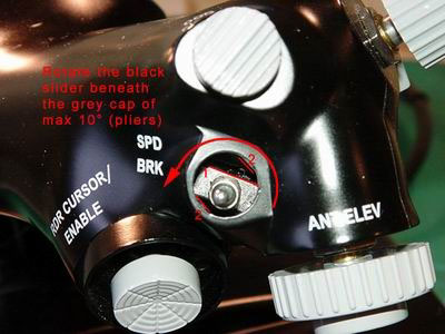
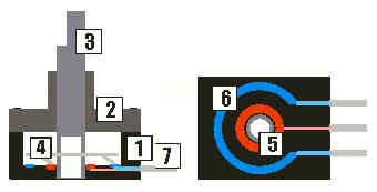
First a little reminder. The T9 position of the switch is meant to be momentary
(it doesn't stay in position). The T10 part must stay in position and is meant
to toggle the speedbrake ON and OFF.
On some stock Cougar, the speedbrake may appear to be reluctant to move and
a considerable force is needed to snap it in its T10 position. We have seen
stock cougars with T10 not staying in its position because the guide was already
broken. This is due to a misalignment between the switch inside the throttle
and the guide and its grey cap. The guide is in plastic and takes all the forces
consequent to the misalignment and it's only a matter of time before it breaks.
When it does, all you have to do is request a replacement part (Ref Guillemot
: #5074748) as long as your Cougar is under warranty but why go through all
the hassles when there are so many ways to avoid the issue.
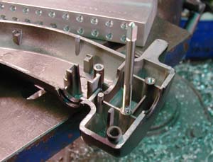
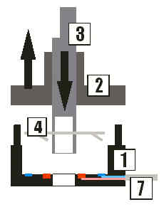
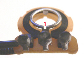
- The easiest solution is a simple rotation of the guide towards the inside
switch so that the misalignment is corrected. I believe Terrapin came with
the idea a long time ago but by rotating the electrical switch inside the
handle, hence needing to take the throttle apart. Personally, I tend to perform
that simple external rotation on as many Cougar I see. It's not always doable
because in some cases, the guide refuses to move but generally, it's working
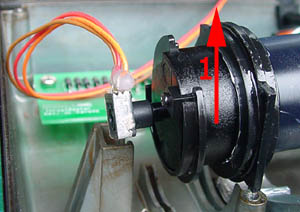
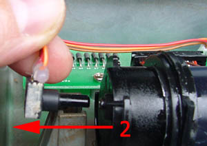
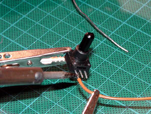
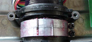
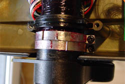
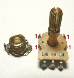
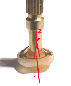
fine. The picture below was taken after removal of a broken plastic guide
and its grey metal cap. The red lines marked 2 are the notches that align
the guide with the throttle handle. Note how the switch inside (marked 1)
is completely misaligned. The solution would be to take a pair of pliers and
rotate (without disassembling) the black guide and its cap of some degrees
in switch direction. Of course doing so you'll somehow damage the plastic
guide notches by reshaping new ones the hard way. That's why you have to go
at it carefully and only a few degrees so that the guide stays in its new
position without moving. Don't rotate the switch back in its old position
because the guide notches are now loose and you may end up with a loose speedbrake
switch. Do the rotation in one swift move and don't go back. The plastic should
reshape itself according to the metal notches of the handle. You don't need
to go all the way, only a few degrees will suffice. Remember, this is not
the best solution, it's the easiest.
- For those not afraid to take the throttle handles apart, you can choose
between moving the inside electrical switch according to the external guide
as Terrapin proposed and you may use superglue to lock the electrical switch
in its new position or you can simply recut new notches in the plastic guide.
This is a relatively simple method and all you really need to be careful for
is to make a clean cut and measure the corrected angle precisely. Use an X-acto
knife to cut the plastic. Sartori23 was the first to explain the modification
on our forum.
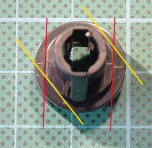
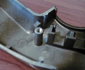
It involves a lot of work mainly caused by dismantling the throttle but it's
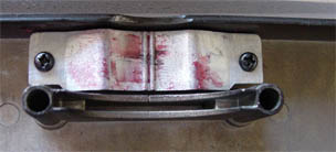
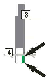
by far the most elegant solution to quote Terrapin ;) The picture below displays
the original notches (red) and the ones that needs to be newly cut. By no
means is the angle here correct, measure yours from your own throttle.
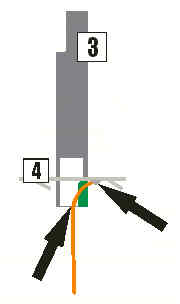
- The third solution comes from Zealot of the CW forum and consists of simply
filing the corner of the notches of the speedbrake guide as displayed above.
Zealot decided to go this way because he didn't want to cut the new angles.
So by filing the corners of the notches to allow a smooth rotation of the
guide on the handle and securing the plastic guide in its new position with
superglue. This modification also involves the dismantling of the throttle
and is very similar (but more elegant) to the forced rotation of the external
guide explained first. Zealot gives a full methodology here.
From all the solution here, my preference
goes to Sartori23's because it's the most logical and the one probably safer
for the longevity of the speedbrake switch. Remember, measure twice, cut once.
And finally - IJ made some new casing in aluminium - more info here
|
|
|
|
|
Cleaning the pots has been covered in the Hardware FAQ section, so go there
and see if you can clean them. It's probably worth to add that some users use
electronic products to clean and lubricate the stock pots. Antix uses DeOxit
to clean and somewhat repair the damaged resistive surface of the pot, and provides
a little lubrication. Then Cailube
to lubricate and protect the pot in the long run. In Europe, Similar products
are available in the kontact
range. I use Kontact 60 to clean the pot, KontactWL to rinse the pot and Kontact
61 to lubricate. It's worth advising to always work on a disconnected Cougar
and if you decide to use products to wait until the pots are dry to reassemble
them.
If the pot problem is unbearable to you, you can replace the stock pots with
CubPilot Hall sensor. Read more about that in the hardware mod section below.
|
|
|
|
|
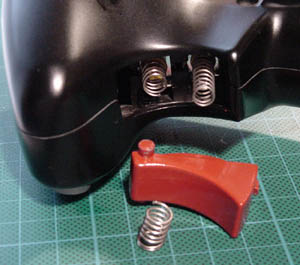
Some users (me included) regret the dual trigger positive feel of the F22 and
James provided a simple adaptation of the F22 trigger system to our Cougar.
The positive feel is lost on the Cougar due to the absence of spring between
the microswitch and TG2. James cut a third of an old FLCS handle spring and
inserted it between TG2 and its microswitch to regain that positive dual trigger
feel. Some trial and error may be required to have the required feeling but
it's very easy to do and quite efficient. Thanks James.
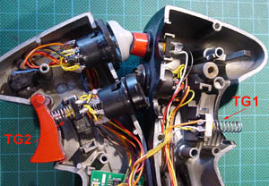
Now the obvious question arises if you have no spare FLCS! The
easiest answer is to replicate what was done on the trigger of the FLCS. TG2
has no spring but a lump of compressible foam that did the trick. So inserting
a lump of foam between your Cougar TG2 and its microswitch should do alright
also. For those of you really needing a spring, you'll have to try to find something
similar to the TG1 spring and cut it to the desired length. Best bet is R/C
modelling, or specialized spring stores. I might add that I found plenty of
suitable springs in a Allen key ring. Read the full discussion here.
|
|
|
|
|
The throttle detents was something I really looked forward to during the beta
test. Now, since I fly mostly when the whole family is asleep, I try as much
as possible to minimize the noise of the detents. We'll see how to that that
later. First here is how to set the two detents at desired position along the
throttle course. We have two detents, one for the idle position and one for
the afterburner position. The factory setting are quite off and the idle detent
needs to be moved back and the AB detent needs to be pushed forward so that
the full military course is longer.
1. Setting the detents
Let's start by marking the position where we want to place the detents. Like
everybody else, I took advice of this early thread
to make my own method. Place the throttle at the exact spot where you want to
the detent to be placed and place two piece of tape on the throttle as displayed
in the pic below. Then mark by a common reference the relevant spot. Repeat
the marking for the other detent.
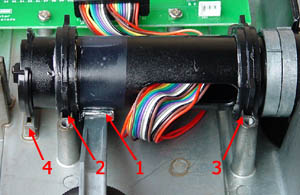
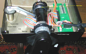
Next place the throttle in minimal tension with the wheel just below the Cougar
serial number. The throttle will be taken apart and since we need to work inside
the throttle with the handle in place, we need to find a good support for the
throttle. I hope you haven't throw away the Cougar box because the inside styrofoam
is the best support you can get. Start by unscrewing the 8 screws from the cover
of the TQS then place it apart.
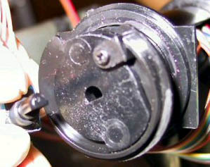
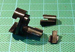
The detents are composed of two circular locking rings (one for
each detent) that envelop the axle of the TQS handle and a semi-circular metal
pressure-plate screwed inside the throttle base cover. Each locking ring has
a protruding notch that causes the detent effect when passing through the two
ridges on the metal pressure-plate placed about 1-2mm apart. To move the detent,
we simply need to rotate accordingly the corresponding locking ring along the
handle axis. Do it one detent at a time. Unscrew the locking ring. You don't
need to go much farther than one or two turn, just enough to allow the ring
to rotate freely.
Next, place the throttle arm so that the marks you draw on the lower detent
are a perfect match, hold the throttle arm in position and place the protruding
notch of the corresponding ring to the apex of its course (I mean the highest
possible point) Screw the locking ring in position. Repeat the process for the
AB detent. At the end, you should have a bigger separation of the two notches
- hence the longer military course.
Before reassembling the throttle, a good idea is to apply a generous
layer of grease on the detents to prevent excessive wear. Teflon Plastic grease
has been reported to be of a good brand. Screw back the TQS base and you can
now test your detent positioning.
2. Removing the detents
In some cases, the detents need to be removed. This is easily
done by rotating the locking rings so that the notches don't come in contact
with the metal pressure-plate. But the easiest solution is to simply remove
that metal pressure-plate by unscrewing it and taking it off the throttle base.
Don't forget to remember where you stowed it away; you might need it back at
a later time.
3. Decreasing the detents noise.
When Alice and our daughter Marine sleep peacefully, afterburner
is prohibited. Just like the real thing. After 10PM, we take off in full military
power and we don't go burner in combat by fear of giving away our position due
to the long flame.(except that in my particular case, it's not the long flame
that I'm afraid of ;) )
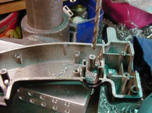
I tried to screw the metal pressure-plate harder so that is sits more below
than it's original position but the noise level stays about the same. Then I
decided to remove one of the two ridges on the metal pressure-plate so that
I don't hear a definitive "click - click" when passing a detent but
only one "click". That's half the noise and besides I like it better
that way. To remove one ridge, I used a mini drilling machine of the proxxon
brand that I quite often use for modelling. But if you don't have such a tool
(or a Dremel as Chakir) you can simply file the ridge away with a hand tool.
The metal is very soft (probably Zamac) and is easily sanded away.
Chakir, from the Mods and Tweaks condensed thread
also brings the solution of placing some o-rings between the metal plate and
the rings to decrease the noise. I haven't tried that one but certainly will
in the near future.
And finally, there is a way to make the presence of the detent
user adjustable by mounting the metal plate on a screw elevated base that allow
the users to lower the metal plate until the detent are not in contact anymore.
More information can be found on the
webiste of Jarno "Rekku" Laakko.
edit: Thanks to Jamf who looked in the Cougar Number
database, we believe the author is Rekku - Good Catch Sherlock ;) - That is
now confirmed by an email from the author: Jarno "Rekku" Laakko
|
|
|
|
|
Spring play was discussed by Guillaume Lelevé
in his play article available completely from the unsupported
files section, here is a snipped relative to the spring play:
If you've owned or are the owner of the original Thrustmaster
F-22 PRO joystick, then you'll probably be aware of this type of play already,
and this section will be of interest to you. ? Thankfully the Cougar is far
more resilient to developing this type of play. Spring play occurs as a result
of the way several mechanical components interact inside the stick. In an ideal
world it would never occur or develop, but what’s good on the blueprints
sometimes doesn't materialise in practice. With the Cougar’s spring and
gimbals system, the only region in the stick's movement where play can occur
is at the centre of travel. It is important to realise that if you have this
kind of play, it will not generate any play in terms of the axis value seen
by Windows or your game. The play only concerns the central resistance, not
the potentiometer. Take a look at the diagram below which shows the gimbals
system from a side view.
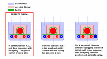
The gimbal/spring system consists of a base gimbals with two "poles,"
a joystick gimbal also with two poles, and a spring which connects the two and
touches all the poles. The objective is that in the joystick's centre position,
all 4 of the poles are in contact with the spring. If one or (worse) two of
the poles aren’t in contact with the spring in its centre position you
will have some degree of a play, from an almost impossible amount to detect
to a horrible few degrees. The bigger the distance between the spring and the
non contacting pole, the greater the degree of play you'll observe.
For this type of play, the difficulty is to identify the part responsible for
the play. Here's how to do this:
- Check and remember the axis you want to inspect - is it the X axis or the
Y axis?
- Open the base of your stick by removing the 4 screws (tip : remove the handle
for this kind of manipulation it will be more comfortable)
- Locate the joystick gimbal you're interested in investigating and try to
rotate it with your fingers. If it is not possible to rotate the gimbal on
this axis, there’s no play! Try to find another type of play (see lower
axis play, and X axis play). If the gimbal moves freely on a very small travel,
you need to investigate and modify the offending part. Generally it’s
going to be either an axis gimbal pole, or the base gimbal pole. If you take
a look at the previous diagram, you’ll see the principle reasons for
spring play. Keep in mind that the objective is to have the 4 poles in contact
with the spring when the stick is in its centre position. If the gimbals are
in fact all OK, then the problem may lie with the spring itself. Be sure that
you use default springs.
- To fix the problem, all you need is a material that can be placed on or
between the parts. Usually a thin resistant material (plastic, metal, avoid
paper) is recommended
- Proceed via successive test until you reach the perfect result (usually
thickness). I usually use plastic sheet for this kind of task. Once you have
found the good thickness you have to fix it in place with special glue, twist
wires, whatever you have at hand.
I might as well add my own experience with spring play. It's very difficult
to detect on a stock Cougar and I didn't notice mine suffered a bad case of
spring play on my main unit until installing IJ Über mod. I tried different
ways to increase the size of the relevant plots on the gimbals so that the spring
touches all fours. But ultimately, I followed IJ advice to bend the spring instead
of changing the shape of the plot.
|
|
|
|
|
Jagstang rotated his Hat2 (TMS) and Hat3 (DMS) to better mirror
the real F-16 block 50 handle. Hat 3 was rotated 45° by taking the hat apart
and cutting the alignment rod. The Hat was then glued in its new position. The
TMS (Hat2) just needed a 10° rotation and Paul cut the lug off the barrel
to allow the rotation but didn't need to glue it on since it was a tight fit.
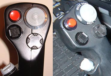
On the picture above, you see Jagstang's Cougar handle and the
real one. Thanks Paul for sharing this with us.
|
|
|
|
|
The rubber boot at the base of the stick
is partly responsible for the stiffness of the stick, at least past the 85%
axis range. Some users reported that removing the rubber boot increased their
positive feeling about the stick so here is how to remove it:
- Disconnect the Cougar from your computer or USB hub.
- Unscrew the handle.
- Remove the 4 screws from the metal base ring.
- Lift off the rubber boot.
- Reassemble.
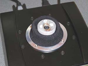
TMHawkins was the first to place a sock (not a smelly one,
mind you) in place of the rubber boot. The full procedure can be found here,
Thanks for sharing.
Hellcat came with a mod of a new kind - replacing the rubber
boot with a can cooler, Here is how it's done:
The replacement boot is a Neoprene Can cooler turned on its head, trimmed and
glued to the ring that holes the original rubber boot, the hole operation took
about an 1 hour, it took me longer to fine a Can cooler, for you people in the
USA and Australia there should'nt be any problem. We have no need in the UK
for can coolers, the weather is never very warm!
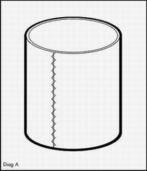
I have noticed on my epic journey for the can cooler that some have Zig Zag
stitching and some have a double seem, I used the Zig Zag stiching version,
less bulky.
OK lets start, I hope the instructions are clear!
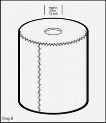
1. Start with your Can Cooler (Diag A) turn the can cooler
upside down so its standing with the base facing upwards (Diag B).
Cut a circle 3/4 inch about 20mm in the center of the base, I've noticed that
some can coolers have a hole already in the base, if this is the case all well
and good just make it slightly larger if necassary (Diag B).
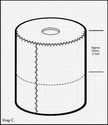
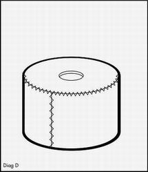
2. Once the hole in the base is complete, we
can cut the can cooler down to size. Measure from the BASE down 2 Inches approx
52 mm (Diag C) and cut around the can cooler, you should end up with a 2 inch
hight can cooler (DiagD).
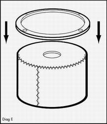
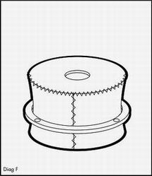
3. Almost complete, Push the metal ring from
the original rubber boot over the can cooler (Diag E) down (Diag F) until you
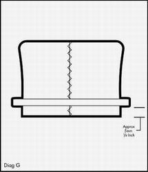
are about 1/4 inch about 5mm from the bottom of the cooler (DiagG).
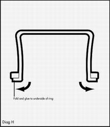
4. Now fold back the 1/4 inch / 5 mm surplus
(Diag H) and glue to the underside of the ring, once the glue is dry push the
tip of a modelling knife through the screw holes and cut the neopren to allow
easy access for the screws. Place the glued ring and new cover on the Cougar
and screw down in place (Diag I).
 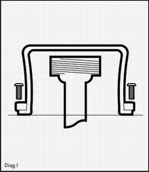
5. Once the new boot is in place you should be
able to stretch hole in the neoprene top that you cut in section 1 over the
Cougar Joystick attachment. I have noticed that once the original rubber boot
was removed there was a noticable 'clunk' as you moved the joystick around and
it made contact with the base, obviously the original rubber boot cushioned
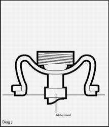
some of the noise. I got around this by using a rubber band with some double
sided tape and placing it around the stem of the joystick (Diag J).
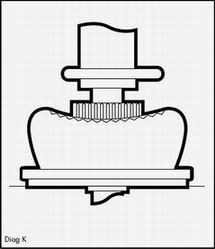
If all has gone well you should end up with something that looks like the final
diagram! (Diag K).
6. Go and get some flying in.
|
|
|
|
|
As you know, there are two kinds of CH
pedals on the market: USB and Gameport. The Cougar allows to connect a gameport
rudder on the base of the stick, So I'll develop here the modification of this
later version. Mind You Cubpilot has a procedure to modify the USB rudders to
use with the Cougar on his website.
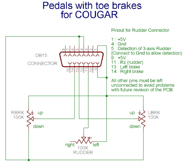
Lapin was the first to do some reverse engineering on the Cougar to get the
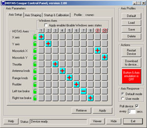
correct wiring diagram. He came up with this drawing (click to enlarge)
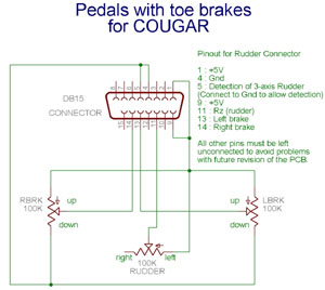
The drawing is very well done and quite clear, the only problem
I had while performing my first conversion is the DB15 orientation. You have
to consider the drawing as if you were looking at the back of the connector,
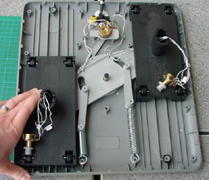
not the front as my newbie skill at electronic dictated me ;) The fist step
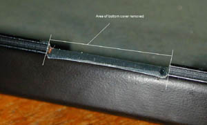
is to take the rudder apart. Geez, it's not easy and it takes some time. The
pedals need to be dismantled as well to allow the two large plates to be separated.
We would have to do it anyway since the toebrakes pots are in the pedals. When
the rudder is dismantled you have two choices as far as the wiring is concerned.
You can use the CH wiring or you can rewire the whole thing. I prefer the latest,
I feel it much less confusing and it allows us to follow exactly Lapin's drawing.
Still, if you want to stay on the safe side (to allow an easy come back to a
unmodified rudder) you can use a spare DB15 cable (I took mine from an extension
cable from which I cut the female connector). The cut wires are inserted in
the CH rudder in place of the original cable and tightly secured in place.
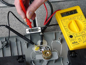
Then comes the marking of the corresponding wires (colours/pin
number) To do that, use a multimeter and place one end on the pin on the DB15
connector and the other end of your multimeter against the first wire at the
other end of the cable. When both multimeter ends are on the same wire, the
display should report connectivity and you know you have the correct colour/pin.
So check all the wires with the same pin until the multimeter shows connectivity.
As soon as you find a correspondence, write it down and don't hesitate to make
a small drawing. Only seven wires are of importance, so as soon as you know
which colour they refer to, you can cut the others short and isolate them. (You
can also wait until the mod is finished before cutting them in case you made
a mistake). I don't know if the DB15 extension cables have all the same colour
codes but here are the combinations I found:
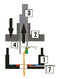
Next step is quite simple, follow the diagram carefully and solder
the wires correctly. You have to heat to wire before applying the solder, and
not the other way around or you'll end up with a cold solder. Use an electronic
soldering iron and keep its pointy end clean with a small hard and dry sponge.
When you weld two wires together, don't forget to isolate them. I used tape
but it's best to use shrink tube especially made for that.
When passing the wire into the pedals to reach the toebrakes pots, do take care
to allow a good length of wire so that the pedals (rudder action) can move freely
forward and backward. Use the CH wires as a visual guide and don't hesitate
to use the CH pin to guide the way of your wires on the different CH parts.
That's it. Do test the mod with the Cougar before reassembling
to ensure that it's working right and that you won't have to take the rudder
apart once too many. If you realize that the rudder or the toebrakes direction
is reversed, you can inverse the solder points on the relevant pot or more simply
reverse the axis within the CCP.
Once you're sure that everything is working with the Cougar, you can start reassemble
the rudder. First ensure that both springs are correctly in position and that
all the moving parts fit nicely together. Check that no wire can be damaged
by screws and place the cover plate on the rudder. At this point I like to tape
the two covers together so that I don't risk the parts inside to be separated
when I flip the rudder on its back to screw it tight. Start by screwing the
two lower centre screws to secure the springs then work your way up and finish
by the exterior lines.
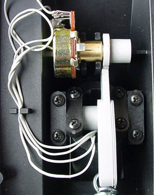
Next comes the pedal assembly. Slide the pot into the pedal and place the spring
in its place. Protect the wires and secure the pedal on its mount with the 8
screws. Then position the pot by ensuring the contacts are upwards. Align the
dented wheels together so the pot is in its centre position when no pressure
is applied on the toebrakes.
Finally snap the wires in the guide and screw back the pedal cover.
As soon as the second pedal is reassembled, you can go flying a little, you
deserved it. Remember, your first kill is for Lapin who came up first with the
circuit's blueprint.
|
|
|
|
|
The Über Cougar was the first solution brought by famous
Über Meister Ian Johnston's to remove lower axis and X axis centre play,
as well as to reduce wear within the gimbals. This is achieved by re-machining
the gimbals to much tighter tolerances with brass surfaces and roller bearings.
By the way, it doesn't matter how much wear you currently have with your gimbals,
as Ian replaces all the wear surfaces.
Today the Über Cougar is the best solution around for those wanting to
get rid of the annoying centre play problem, it's efficient, affordable and
quite easy to install. The only drawback is that Ian is now quite busy with
the Über2 mod (see below)
and the Über Cougar is only available as a special order. So get one while
you still can. It's worth mentioning that the Über mod will work with stock
pots or with Cub Pilot Hall sensor (see
below)
To order, you'll have to contact IJ by email
and he will let you know the price as well as how to proceed. Your stock gimbals
will need to be removed from your Cougar and sent to Ian so he can remachine
them. Provided Ian lives half a globe away, the transit is quite fast but may
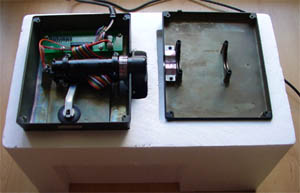
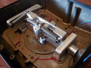
vary according to Ian's timetable. Here are some pictures of the modded gimbals
and the reassembling in my Cougar.
Above are the parts upon return from down under ready to be reassembled
in my Cougar.
The parts where they belong. It's important to let you guys know
that the Über Cougar is very hard to move on the first hours of use. Indeed,
in my case, the Y axis refused even to come back at its centre position. Still
after some time well spend flying around the stiffness disappeared progressively
and the feeling of a Cougar without centre play is really worth the effort and
price. It's recommended to replace the grease after some hours of use to eliminate
all the small metal particules that spoiled the grease during the early stage
of normal wear.
The biggest advantage of the Über Cougar is the deletion
of the annoying play. There is still a transition between X and Y near the centre
of the axis that some find annoying. That's why IJ pressed on with the design
of the Über1 that is now discontinued in favor of the Über2.
Bear in mind that these mods are much more expensive. Contact Ian
for pricing and how to proceed if you want to order the Über Cougar. Payment
is done through Paypal.
If you want to read more info about the Über Cougar, do read
James review of his
set.
|
|
|
|
|
Some people have noticed a wobble or play in the handle mounting
above the big grey nut and in an attempt to stop this have over tightened the
handle screws. The handle material is quite soft and this combined with the
fine threads used will strip the thread, what follows are the basic steps I've
taken to fix this.
- Step 1: obtain either a recoil or a helicoil kit in the correct size 3 mm
x .05 I get mine from RECOIL
AUST They have outlets worldwide , the HeliCoil brand also have the correct
size.
- Step 2: You need to strip the handle so that you have a bare right hand
section, The only tricky part is the fore finger (S1)button/switch.To remove
this pop the button off from outside using a small screw driver, Then push
the 2 prongs on the switch together so the switch is free from the handle
half
- Step 3: Once the right side of the handle is stripped refer to the instructions
included with the recoil kit for the correct size drill (in this case either
3.2 mm or 1/8") I used a small bench drill to do mine but if very careful
it can be done with a hand drill, You need to make sure the hole is straight
- Step 4: Once the holes are drilled to depth (I drilled to the bottom of
the existing holes) Use the provided tap, Again I use the drill press to start
the tap turning it by hand this ensures it's straight.
- Step 5: Referring back to the recoil instructions install the inserts keeping
pressure on the tool as it turns to keep the insert compressed.
- Step 6: Reassemble the handle being careful to make sure all wires and switches
are in their correct places, Tighten screws and have no handle play ;)
Thanks Ian for bringing a solution to this annoying problem some have encountered.
|
|
|
|
|
Morten "Goose" Kielland contacted me about doing
a write up of his solution to the stickiness of the throttle. Since I hadn't
found "the" solution to that annoying problem, I decided to give it
a go and tried Goose's solution with some minor modifications. Be warned It's
not an easy thing to do but I'm happy with the results. Thanks Goose for your
contribution. By the way, I replaced the cold beer from your list with a piece
of chocolate cake ;) let's get down to business with Morten's guide:
As most Cougar owners must have noticed, no matter how hard you
try, you just can't move the throttle that little fraction of an inch that you
sometimes need. Try it yourself: Push (or pull) the throttle handle with steadily
increasing force until it starts to move. And what happens? It jumps. Not much,
but still, it jumps, suddenly and uncontrollably. Which of course prevents you
from getting the exact power setting you need, for instance when trying to get
your Falcon connected to that tanker in the air. Of course, refueling in the
air is rather a large order, but a sticky throttle doesn't exactly make the
job any easier for you.
So, what to do?
There are several ways, actually. Some easy, but perhaps not-so-efficient-ways,
some harder and more efficient. And a few hard and inefficient as well, though.
The easiest solution is just to slacken - or even remove - the four long screws
in the middle of the bottom plate of the TQS. This helps. Some people are quite
happy with that. So try that first! If you are satisfied with this, then all
is well; if not, please read on.
It's all about friction
Friction as such can be divided into two different types: Static and moving.
All materials and surfaces have their own particular friction-characteristics,
and the important part, in our case, is the difference between the static and
the moving-friction for each set of material - or materials - in contact with
each other. For some sets of materials this difference is big; for others, smaller.
A waxed ski on cold snow, for instance, makes up a great static-friction force,
but a very little moving-friction force. In other words, it takes a lot to make
the ski glide from a standstill, but as soon as it glides, it glides; and very
easily, too. (Which is just why cross country skiing is possible - unless you're
skating on your skis, of course!).
Now, here exactly lies our problem: The choice of materials and type of grease
used in the Cougar TQS is most unfortunate in this respect; the materials have
a huge difference between static and moving friction, and the grease which is
applied during manufacture (as a futile effort to reduce this problem?), is
not sufficient by far; and the result is - as we all know - disastrous. In fact,
this is perhaps THE most annoying physical issue concerning the Cougar (perhaps
let alone the center-play and stiffness of the joystick itself).
So what we really need to do, is to change the materials rubbing against each
other inside the TQS. At least, that's what I did, and my throttle is now as
smooth as silk - and still very firm, so that I'm able to rest my hand on the
handle without fear of moving it. It's absolutely perfect!
But how?
Now, before you read any further, just be aware that
if you make any attempt to follow this guide, neither the writer nor the publisher
of this document will be responsible for what might happen to your TQS if you
do. So, if you screw up your own - or perhaps someone else's - Cougar TQS, it's
solely your own responsibility, and you do this totally at your own risk. Be
warned!
That said, unless you're rather clumsy and/or reckless, there's a rather fair
chance that you'll succeed in undertaking this operation. Let's get down to
business.
Firstly, exactly what supplies are needed for the job? Here is a list of what
I used:
- A small pair of scissors
- a screwdriver
- alcohol (as degreaser, mind you)
- some aluminum foil (the multi-layer type with plastic between the layers
is superb; Toppits/Melitta/Cofresco or similar)
- a small knife
- a toothpick
- a file (for metal, about 15 mm wide)
- some glossy, transparent, plastic tape
- a small washer (1-2 mm thick, 10-12 mm wide, hole 4-6 mm), almost any material
will do
- a rag (cloth)
- some "bluetack"
- some glue, preferably quick-drying (superglue is fine)
- some thick, liquid soap
- some cigar or cigarette ash (not absolutely necessary)
- good, sufficient, light
- a couple of hours
- a cool beer or two (but not much more!)
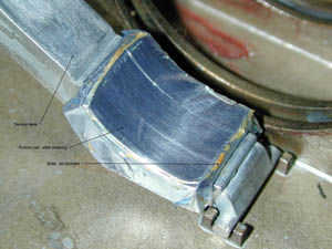
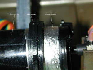
And here is - in short - what I did: I opened the TQS, marked the axle, removed
the pot-meter from the axle, removed one of the bearings from the axle (some
disassembly needed), degreased the axle and bearing, put the bearing back on
the axle, applied glossy plastic tape to the axle, inserted aluminum foil between
the axle and bearings, applied a drop of glue between the foil and the bearings,
dressed the tension-lever rubber pad in aluminum foil, lubricated tape and pad
with soap, inserted a washer under the wheel that adjusts the tension, removed
some of the metal in the casing (because of the new - now lower - position of
the wheel), and put it all back together again. I had to experiment quite a
bit before I got this far, really, but that was some of the fun as well.
Now, half of you have now probably got a pretty fair idea of what I'm driving
at; the rest of you may not even have a clue. But don't worry! We'll take this
step-by-step:
Step 1- Marking the bottom plate, opening the
box and marking the axle
Before you do anything else, disconnect your Cougar and put the TQS to rest
in a safe manner (see illustration below). There are several ways of doing this.
Personally, I prefer to lay it on a corner of a table and fasten it with two
good lumps of Bostik's "Bluetack" (a sticky, blue substance, normally
utilized to stick paper to almost any surface - not HOTASes; but, nevertheless,
ideal for the purpose). The main thing is that the TQS should lie still during
the operation and not slide down and go bang onto the floor or whatever.
When the TQS has been laid to rest safely, first mark the bottom plate on each
side of the small wheel used for adjusting the resistance of the throttle handle.
Slacken the wheel all the way. Then, and not until then, may you remove the
four long screws in the middle, and the four shorter ones in the corners of
the bottom cover. You should now be able to lift the (now marked) bottom cover
off.
Now, mark the (black plastic) axle as well, just 1/2 - 1 mm on the near side
of the bearing being furthest away from the handle (this is where you shall
apply the glossy plastic tape later, after the degreasing-operation is complete,
on the near side of this mark). Use a small, sharp knife for marking. A short
dent in the axle should be quite sufficient, as long as you're able to see it
later on.
Step 2 - Disassemble and degrease the axle, pad
and bearings
Next, you'll have to degrease the axle and bearings, and - not to forget -
the small rubber pad on the tension lever below the axle. In order to get at
least one of the bearings off, you must:
Carefully lift the axle up from it's beddings (be careful not to damage the
pot-meter at the far end!)
Remove the small pot-meter at the far end
Remove the small screw at the end-plate at the far end
Remove the end-plate itself (slide it off)
The bearing furthest away from the handle can now be detached from the axle.
Do not bother with the other bearing, as this is blocked by the ribbon-connector.
Now, degrease the bearing and the axle with alcohol (I cannot recommend acetone,
as this may dissolve the plastic!). The inner bearing (which cannot be easily
removed) may be slid back and forth on the axle, so that the area normally covered
by it may be degreased as well. Now, put the axle down, temporarily, and pick
up the tension-lever and the rubber pad on it and degrease the rubber pad as
well.
When you're happy with the degreasing-operation, move on to the next step.
Step 3 - Applying the glossy plastic tape to
the degreased axle, etc.
Now you'll have to find your mark from step 1. The point is, of course, that
the tape must be applied to the area of the axle which - normally - is in contact
with the rubber pad. Hence the marking - and the degreasing (you won't be able
to get the tape to stick to a greased surface!). I put the tape on all the way
round the axle in order to be certain that it will stay on, and not come off
easily. Make sure the joints are on the side of the axle opposite to the area
that is normally in contact with the pad. Having done that, get a piece of alufoil
and wrap it around the rubber pad. Trim it with the scissors. I made the wrapping
overlap thoroughly on the back side of the rubber pad. Replace the pad, use
a little glue under it, just to hold it in place and make the assembly later
on easier. Apply a fair amount of liquid soap on the dressed pad and the plastic
tape you just put on the axle. A slimy, almost-solid, kind of soap is the best.
Perhaps even hair-shampoo will do? (Haven't tried that, though.)
Step 4 - Inserting the washer and trimming the
edge of the bottom plate
In order to be able to apply greater tension needed to compensate for the
lower friction in the system, I inserted a washer under the wheel which is raising
and lowering the tension-lever arm.
This may not be necessary, especially if you use some kind of powder to increase
the friction. Ash, especially from a cigar or cigarette, should be suitable
for this. However, I must emphasize, I've not tried this on the Cougar; but
it works well on my violin (yes, it's true!) to prevent the pegs from slipping
after soaping. (Soap and cigar ash have been used for at least a hundred years
by musicians for this purpose, the thing is to find the right balance between
the amounts of soap and ash: Too much soap, it slips. Too much ash, and you're
back to where you started.) So if you rather want to try this approach as an
alternative to increasing the amount of tension, please do. But it may take
some experimenting until you're satisfied. And don't blame me if you have to
spend quite some time doing this! (Nor for anything else!) Yet another - and
perhaps even simpler - approach, may be to add some more alufoil or whatever
firm material, between the pad and the tension-lever. I haven't tried this either,
but it may work just as well. It's all up to you. Experiment, if you wish.
If you want to follow my way, however, here's what you do:
Find - or make - a washer, approx. 1-2 mm thick, that will fit under the small
wheel that raises and lowers the tension lever arm. Be aware that this most
likely will prevent the wheel from stopping at its maximum, and, in consequence,
make the arm slip down, and you will have to start turning the wheel again.
This can be remedied by obvious extra fittings, but is not strictly necessary,
so I will not go further into this matter here. When you see the parts, you'll
probably understand what I mean, and what it takes.
Now, lift the wheel off, place the washer under the wheel and replace the wheel.
Replace the lever (with the wrapped rubber pad in place) and go for the metal-file.
Using the file, remove a part of the metal in the bottom plate which is (normally)
directly adjacent to the wheel. This area should now be marked (in step 1),
so it should be easy to remove only the metal conflicting with the wheel in
its new position (see illustration below). How deep you have to cut depends
on the thickness of the washer. Do not use a washer that is too thick, as this
will probably create to much tension in the system later on. 1-2 mm should suffice.
This done, we move on to the next, and perhaps most tricky, part of the operation:
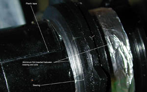
Step 5 - Inserting the aluminum foil
As you might have realized by now, the stickiness of the throttle is not only
caused by the rubber-pad against the greased axle, but also - to a great extent,
actually - by the bearings. Therefore we have to make certain that the axle
will move smoothly inside these as well. This is done by inserting two pieces
of alufoil here, one piece inside each bearing (yes, I know some of you know;
bear with me, please).
Start by cutting two even, clean, pieces of the aluminum foil with the scissors.
The pieces should each be quite a bit broader than the bearings, and - ideally
- as long as the full circumference of the axle (or - more practical - just
a very little bit shorter). You might have to try a few times to accomplish
this perfectly. Also, this must be done before you put the axle back into its
beddings. When the foil is well in place under each bearing, apply a small amount
of glue between the bearing and the foil in order to make sure that the axle
will rotate within the foil, and that the foil will stay in place relative to
the bearing.
Step 6 - Wrapping up - and some bonuses
OK, having come this far, the worst part now lies behind us. With the alufoil
successfully inserted and glued to the bearings, replace the end plate of the
axle (slide it into place), replace the little screw that holds it in place,
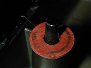
and insert the potentiometer into the end plate. Carefully replace the axle
into its beddings and make certain that both bearings, and the end plate and
the pot-meter enters their respective beddings. Also, make sure that the tension-lever
and the pad is still properly in place and that the wheel is turned all the
way down, i.e. to the smallest possible tension.
Now, get the toothpick, sharpen it with the knife, and insert it as far as
it will go with firm, but careful force, into the small space between the pot
and the wall of the bedding, as shown in the illustration below:
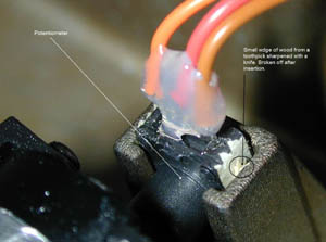
As you most certainly will have guessed, the insertion of the wedge is done
to eliminate any play of the pot in its bedding, so when you pull the throttle
back after it has been pushed forward (or vice versa), there will be no delay
before the pot starts turning. Although this has nothing to do with the friction,
it makes the operation of the TQS even more accurate (which is exactly what
we're after here, isn't it?).
Having done that, you might as well degrease the detent rings and the detent
plate in the bottom casing, and put some plastic tape on them as well. This
will dampen the hideous "clicks" which has kept many a wife, or girlfriend,
or mother, or whatnot, awake during long hours of nocturnal flightsimming with
the Cougar.
For covering the detent rings/plate, I used two layers of tape. The more layers
you apply, the softer the clicks, and vice versa. You can also remove the clicks
altogether by removing the plate from the bottom casing (fastened with a pair
of screws and some springs). Take good care of it if you do remove it; you may
want to put it back later. For maintaining total control of the throttle movement,
you should remove the plate. The price you pay for this, however, is that you
lose the idle/AB detent clicks. I chose to keep them, but in a much softer form,
as explained above.
The choice is yours.
Step 7 - Final reassembly and testing
Done! - almost. If everything has gone well, the remaining part of the operation
should be relatively simple: Replace the bottom cover carefully, making sure
that it enters perfectly. Insert the four long screws in the middle, and the
four short ones in the corners, and tighten evenly and firmly, but not too hard;
especially the four ones in the middle. Remove the TQS from the table, and the
bluetack, and test the operation of the throttle handle. Adjust the tension
if necessary. Hopefully, you will now have achieved a most satisfactory result.
If not, back you go, into the box! But you should know your way quite well by
now, so I'll stop this part right here.
Do not you give in until you're absolutely satisfied, though. It should be
possible to get a totally smooth operation of the throttle based on the principles
I've just outlined. And don't forget the soap!
Good luck! (and don't forget to drink the beer, either!)
A few words on the final
This paper was written as an effort to help other Cougar owners overcome this
irksome problem with the Cougar TQS, and is based partly on my own experiences,
as well as other people's. Some of the information I needed before I started
was collected from different threads in the Cougar World forums, and I should
credit the ones who have fiddled with this problem before me, and who have shared
their knowledge for me to benefit from, but they are too numerous, I would be
sure to forget someone. So, thanks, all of you!
Now, plug in your Cougar and enjoy!
|
|
|
|
|
Many users have asked me a tutorial to install correctly a throttle pot after
having received a spare (from Guillemot or CW). So here's a way to do it. Do
this at your own risk; CW is not responsible of any problem you might encounter
during this operation. Please, as always: work on the Cougar when it is disconnected
from the computer.
-
Step1: Loosen
the throttle grip by turning the wheel seen on the picture below fully to
the right.
-
Step2: Then
you need to open the throttle base. The first thing to do is to fetch your
Cougar box because it's ideal to place the TQS upside down for opening.
If you don't have the box anymore, a table will do but take care not to
let the throttle fall on the ground during the operation. Start by unscrewing
the 4 long centre screws, then the 4 smaller corner screws. Place the cover
on the side and use to store the screws so you don't loose them.
-
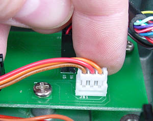
Step3: Locate
the pot and its cable assembly. The pot is inserted in the throttle axle
and is connected by 3 wires to the throttle PCB. The first thing you need
to do is to remove the pot assembly from the TQS. To do so, start by unplugging
the connector from the PCB. Your fingers are enough to do the trick. Maintain
the PCB is place with one hand and pull the connectors (not the wire) labelled
JS1 with your other hand. Yes, I have a third hand with which I took
the picture, why do you ask?
-
Step4: Now
the pot needs to be removed from the axle. Slowly lift the axle from its
place, and if possible, help the pot to lift from its casing as well. When
you judge the pot is free to move, pull it gently out of the axle. Replace
the axle in the TQS base.
You should now have the throttle pot assembly completely
removed from the Cougar. If you bought a Throttle pot from CW, then you should
have the new one with the wires and connectors already installed and you can
go directly to step 7. If, on the other hand, you received your pot from Guillemot
then, you will need to unsolder the 3 wires from your useless pot and solder
the wires to the new one, read on...
- Step5:
Unsolder the wires from the old pot. Obviously, you need to first remove the
silicon from the solder points. I used a Xacto blade to do that. Before unsoldering,
make a drawing of the colour of the wires attached on the pot. You will need
to solder the new pot with the same colour combination. If you want to be
sure, you can unsolder one wire and directly solder it to the new pot, on
the same contact instead of unsoldering the three wires before soldering them
on the new pot.
Use a soldering iron for electronic, it doesn't have to be powerful. A 15W
is enough. The biggest factor is the precision of the tip of the soldering
iron.
Let's do it. Use a pair of pliers to maintain the pot in place, take one wire
between your fingers (not too close from the solder point) and place the soldering
iron on the contact point of the wire on the pot. If your soldering iron is
warm enough, a small amount of time is necessary. As soon as the wire disconnect,
remove the soldering iron. Repeat the process for the two other wires.
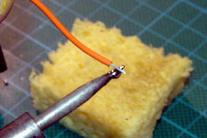
- Step6: Now that you have disconnected
the pot from the wire assembly, we need to solder the wire assembly on the
new pot. Install the pot into the pliers so it doesn't move during the operation.
Place a small amount of solder on the first naked wire, make sure the weld
is going around all the wire and doesn't form a big drop of material on the
wire.
- Place the wire presoldered on the pot contact and place the tip of the
soldering iron on the other side of the pot contact. By heat transfer, the
weld on the wire will melt and get in contact with the pot contact. Again,
if done correctly, the soldering iron doesn't need to stay in contact with
the pot for a long time. Check the solder, it has to be firm and glossy, if
it's dull, then you have a bad solder and you need to start again.
When you solder, you always have to work with a clean solder tip (I use a
wet sponge to clean it). Use small amount of weld and don't keep the soldering
iron in contact with the electrical component too long. Usually, you don't
touch the weld with the soldering iron but work by using the heat transfer
characteristic. A last word of recommendation: don't burn yourself. Avoid
touching the components too close from the solder points, and don't try to
catch the soldering iron if it falls on the ground, run for cover and catch
it when it's not moving anymore. ;) Repeat the process for the other 2 wires.
- Step 7: Once you have checked
that all solder points are good to go, then you can reassemble the pot into
the Cougar. Start by centring the pot shaft and insert the pot into the throttle
axle. Check the alignment before inserting. There aren't a lot of ways to
get it right.
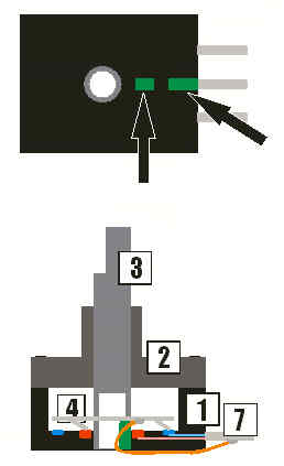
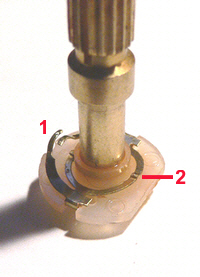
- Step 8: Then replace both
the axle and the pot in their respective place. Beware of the throttle brake
pad (1) that need to be correctly in place as shown on the below picture before
replacing the throttle axle. Align the two rings in front of their notches
(2&3), align the throttle stop (4) and the pot and replace the axle in
it's original position.
- Step 9: the original TM throttle
pot had a small plastic tape around to overcome the tolerance in moulding
the pot casing. You can replace one around the new pot as well but personally,
I prefer to secure it in place with a flat toothpick as Goose explained on
his smooth throttle tip above in this page. Whatever way you decide to go,
I feel it's best to secure the pot in its casing otherwise you will have some
play in the throttle course.
- Step10:
Now connect the pot to the PCB by inserting the connector JS1 into the receiving
contacts. Only one possible way to do that.
- Step 11: Replace the cover,
screw the 4 corner screws, then the 4 inner screws by taking care not to screw
them too tight and you're done.
|
|
|
|
|
Igor "Roto" Savs posted a procedure to repair a pot after failure.
It can be flash damage or the damage occuring without having flashed the Cougar
but after a long period of no use of the kitty.
Beware, the procedure is not simple and is intented for the technically inclined
guys - On the other hand, once your pot is dead, you have nothing to loose :)
You just need a steady hand, good tools and a good pair of eyes as well - or
magnifying glasses :)
But before we start, just one warning: Neither Roto, nor
CW will take any resposibility if something goes wrong - Do at your own risk...you
know the stuff.
- Step 1: How to examine if your throttle pot is bad?
This one is simple, because you probably noticed it already. Just open Joystick
Analyzer and check if the physical movement of the throttle handle corresponds
with the movement of the cursor/bar/number which represents THR axis from
0% to 100% and back to 0%. If both movements (handle and cursor) are simultaneous
without ANY delay, your pot is OK, otherwise it is probably not OK and it
might need replacing or repairing.
So, your pot is not OK...and you decided to repair it. Continue.
- Step 2: Taking pot out of the throttle
Open the base, lift the handle, pull the pot out of cylinder, disconnect it
from the PCB. That's it. If you need more details (pictures) about dismantling,
just look above on the procedure to install a new pot.
- Step 3: Taking throttle pot apart
First, anatomy of a pot:
1 - Base (plastic, PCB)
2 - Cover (plastic)
3 - Spindle (plastic, hole from below)
4 - Contact ring (metal)
5 - Inner graphite ring
6 - Outer graphite ring
7 - Connector (metal) |
 |
Looking at the previous picture I could explain what was wrong with the
pot. I checked conections between outer ring (6) and outer connectors (both)
and between inner ring (5) and middle connector with my Ohmmeter. I discovered
that outer connections were OK, but inner connection was 0. THERE WAS NO
CONNECTION AT ALL. So I concluded that this connection (light red color
on the picture) was interrupted (maybe burned out as an outcome of a electric
overload???) somewhere between inner ring and middle connector and therefore
should be restored for the throttle to work again.
Let's do it:
Cover and base of the pot are connected with 4 heated pins. Just use a small
screwdriver to pry them apart. Be careful not to break any of the pins.
Remove spindle from cover.
- Step 4: Making a notch
Use a sharp knife and cut max. 1 mm wide notch into the spindle wall from
the underside to the height of the contact ring. The notch should look forward
toward connectors when the spindle is in the central position (check upper
flattened part of the spindle). Be careful not to cut to much or crack spindle
in half.
- Step 5: Soldering - part one
OK. Now let's play swiss watchmaker for a minute. Take A FEW (approx. 10)
"hairs" from the stripped electrical flexible (soft) wire (they
must be as thin and flexible as possible), roll them together and cut them
on both sides so that you'll have 2 cm long wire. Now, solder one end to the
underside of the connector ring (you must be really careful and precise when
soldering, because to much solder will obstruct spindle turning action). The
other end of the wire should go through the notch that you cut and down the
spindle through the hole.
Now would be a good time to take the base of the pot and check
surfaces of both graphite rings for dirt and scratches. Clean/grease them as
necessary.
- Step 6: Putting it all back together
Well, put all back together in the oposite direction. Slide the spindle into
the cover and push the cover back to the 4 pins of the base. Be careful to
correctly position the spindle (it must be in central position, not turned).
While holding the cover and base tightly together with your fingers, check
if the spindle turns fully to left and right smoothly and without obstruction.
- Step 7: Soldering - part two
Now all you have to do to finish this bold venture is to solder the other
end of the wire to the middle connector from below. But before you do that,
you'll have to make a small cut into the base underside so that the wire will
be flat with the base. (It is important for the correct placement into the
throttle casing). Do not cut too much into the base (the wire should be very
thin).
-
If you want you can heat the 4 pins to firmly connect cover with the base,
but I prefer the ordinary carpenter's tape and just apply it around and
around the pot. The tape is also useful for tight fitting into the casing,
although a piece of a toothpick is much better than the tape to minimize
the pot play in its casing.
Before you install the pot back into the throttle, use an Ohmmeter to check
the resistance of the pot: connect one terminal to any outer connector and
the other terminal to the middle connector, set 2000k on the meter and turn
the spindle; the meter should read smoothly from 0 to around 85k .
OK. Thats all folks. I hope that this will work for you as good as it worked
for me.
- Step 8: ...
Now go back into The Matrix and enjoy.
An alternative to this procedure would be to use conductive glue to recreate
the bond between the inner ring of the pot and the centre pin. It still needs
to be tried out but it should be much easier than doing the soldering. Anyway,
thanks Igor for submitting this tip. A last word of advice, whenever you dont
use your Cougar, place the throttle handle at a quarter of its course, never
in idle or full AB....
|
|
|
|
|
Here is a copy of a post made by Ernest "Cubpilot" Smith on the forum
about a reluctant antenna pot showing a bad range and no center detent:
Below is what I did and observed in the analyzer:
- Starting with the ANT knob turned all the way CCW = 65535 in the analyzer.
Moved ANT knob one "rib", on the knob, CW (thumb forward) = no response.
- Move ANT knob another rib, on knob, CW (two ribs total) = after 38 seconds
reads 32767, stops for a bit, then after 7 minutes reads about 58000+ and
then the reading goes up and down slightly, after 8 minutes it reads 65535,
then moves back to a lower value and the readings move up and
down slightly again............all this time
I have not touched the Cougar at all after moving the ANT knob two "ribs"
CW!!!
- Starting at full CW position = 0 but then the readings move up to 29183
after 2 minutes (knob still all the way full CW).
- Move knob very slightly CCW (thumb back) and the reading goes to 0 very
fast and stays there.
- Moving it CCW further results in a very laggy response.
WOW!!!! I could not believe what I was seeing. Maybe a trip to the eye doctor
was in order. So, I took the ANT pot out of the throttle handle and disassembled
the pot.
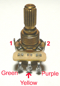 
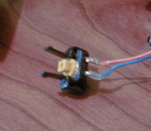
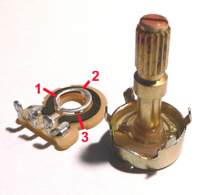
Pictured above is the ANT pot. The picture on the left shows it
assembled. Note the two tabs (1)
& (2). Tab (1)
is longer than tab (2). The wiring
is also shown. In the picture above and to the right (1)
points to the indentation in the pots "can". It stops the shaft from
turning all the way around.
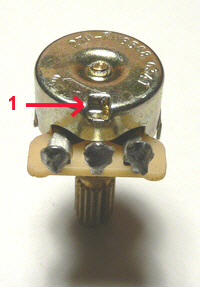
To take the pot apart use a small screwdriver to pry the four
tabs (1) open and remove the metal
bushing as shown in the picture above.
The picture above shows the insulation/resistance assembly taken
off the pot (at the left in the picture). The tan colored material is insulation,
the black semi circle is the resistance material. Note that the metal ring in
the center is supported by three tabs (1),
(2), and (3).
Remember this as it is important to the problems this pot had.
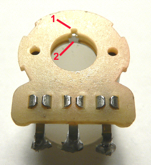
Pictured above is the insulation/resistance assembly turned upside
down. Tab (2) corresponds to tab
(2) in the previous picture. As
you can see tab (2) above has
a small tab on the end of it. This is supposed to fit into the notch (1)
in the insulation board.
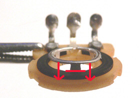
The picture above shows why I was getting such wacky readings
in the analyzer. I didn't want to bend my center ring on my pot for this picture,
but on the pot that was having these problems the center ring was pushed down
to the red horizontal line because the tab (2), in the previous pictures, was
not bent out enough to rest on the insulation board. The metal ring was very
close to the black resistance material. The other two tabs were adjusted correctly
and doing their job. I gently bent tab (2)
out a bit so it would rest on the insulation board and properly support the
inner metal ring. This fixed the erratic readings in the analyzer.
My guess is that there was some arcing from the resistance
material to the area where the metal ring was pushed down which may explain
the odd readings in the analyzer.
OK, now let's look at the center detent problem. The picture above
shows the notch in the metal ring (1).
This is half of the detent system.
In the picture above, the bump on the inner metal ring wiper (2)
goes into the notch in the metal ring on the insulation board, this is the other
half of the detent system. The two wipers (1)
touch the black resistance material.
I tried bending up both sides of the inner metal ring wipers (2)
and it would improve the center detent. However, after the ANT knob was installed
the center detent would disappear completly, or nearly so.
In looking at the design of the pot I could not understand how putting on
the ANT knob would wipe out the center detent. When pushing the knob onto the
pot shaft it would be pushing the metal wipers away from the insulation board/resistance/metal
ring. How could that bend the center/detent wiper back (flatter than when I
had bent them up)?
I could understand the center/detent wiper being flattened when the ANT knob
was taken off, but not when putting it on. I was totally confused .
In thinking about this I thought about the amount of end play the pot shaft
had (shaft movement in and out of the pots body) as compared to my older Cougars
ANT pot shaft, which had very little end play. This problem pot had tons of
end play. This seems to be another item that has been reported concerning the
lack of a center detent (pulling or pushing in on the shaft).
So, how to fix this?
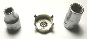
The picture above shows what I used to "adjust" the
pot shaft end play. As you can see it involves the metal pot "can"
and two sockets, one large, one small. Since this pot had too much end play
IMHO, I wanted to reduce it somehow.
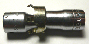
The picture above shows how I reduced the pot shaft end play.
I have to apologize for this picture. I got the sockets mixed up when I took
it. To decrease the pot shaft end play the bigger diameter socket should be
positioned to the left, the smaller socket to the right, not as shown in this
picture. Then, using a vice, center both sockets on the pot "can"
and apply a small amount of pressure to slightly push the bottom of the pot
"can" inward. If you go too far just reverse the sockets and push
the bottom of the pot "can" back the other way. By using this method
I was able to adjust my pot shaft end play to 0.0015" (0.03mm). If it had
a bit more end play it would not hurt IMHO, but don't reduce end play to zero.
If you try this, I highly recommend that you DO NOT
try to make this adjustment using the sockets and a hammer.
You will have no control over how much you adjust the pot "can", not
to mention keeping things square. Only use a vice to make this adjustment,
you will have much better control of the force applied and the bottom of the
pot "can" will remain square.
This seems to have fixed the detent, even after pushing the ANT knob onto the
pot shaft. However the detent was not quite as strong as on my older Cougar.
Here is how I increased the center detent strength a bit. In the
picture above I used a #60 (0.040", 1.01mm) drill bit as represented by
(1). The butt end of the drill
(the part that would go in a drill chuck) was inserted under the "bump"
in the inner wiper. I then used my finger nails to push the metal wiper on each
side of the drill down simultaneously, thus increasing the height of the "bump"
a bit.
I now have a very nice center detent that matches the one in my older Cougar!
A note concerning the ANT knob. If it goes on really hard you can squeeze the
ANT pot shaft a little closer together (it has a slot in the splined end of
the shaft). If the ANT knob is a loose fit, spread the pot shaft a little using
a flat screwdriver. Oh... one more thing, when putting the ANT knob on the pot
shaft, or taking it off, it probably would not hurt to make sure that the pot
shaft is in the center detent. This should prevent the bump on the center ring
contact from getting flattened out. The theory being, if it is in the notch
on the metal ring it would be hard to flatten it thus decreasing the feel of
center detent.
My conclusions are that there may be a manufacturing problem with the pot with
two items. Namely, the tabs of the center metal ring on the insulation/resistance
assembly (my ANT pots tab (2)
didn't support the center metal ring just like on this problem pot described
here). This is two ANT pots that I have seen this on. The pots shaft end play
is incorrect also, IMHO.
The excessive pot shaft end play may be caused when the Cougars are assembled
if the knobs need excessive force to install them. It might be possible for
the bottom of the pot can to be pushed outward, resulting in excessive pot shaft
end play. Or it may be a part (the pot shaft?) that is out of spec from the
pot manufacturer. Either way I hope that TM has informed the parties involved
that there is a problem with the ANT pots and or the assembly of the ANT knobs
and something is done about it.
I guess my purpose in writting this little post (little?) is to point out a
problem with the ANT pot. The wild output of this particular pot is probably
not a common problem, but I have seen two of these pots where the center metal
ring was not supported correctly (that tab #2). The lack of a center detent
is more widespread from what I read on the CW forums. This post also addresses
a way to fix both problems. Now, mind you, I think TM should be sending out
new ANT pots that don't have this center detent problem or any other problems.
But, if you can't get one right away it can be fixed.
I do invite any comments/questions/discussions that anyone may have. Maybe
I'm not looking at things just right or I have missed something
Thank you Cubby - I think you deserve much more than
some rep points on the forum :)
|
|
|
|
|
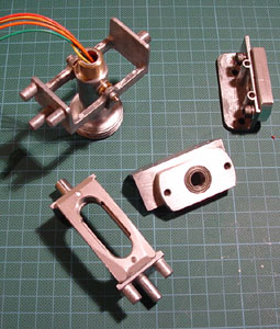
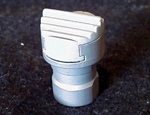
Since the beginning of the Cougar adventure, we need to fix the
speedbrake problem to avoid the housing to break as explained on the top of
this page. Once again, our friend Ian
came to the rescue from down under and machined some housing on his new CNC
mill. Well actually the CNC works alone while IJ pretends to rest or eat or
... :) ! Anyway, the new casing are done in 6061 T6 aluminium and will never
break - Of course, IJ corrected the misalignement problem so the switch should
slide without friction.
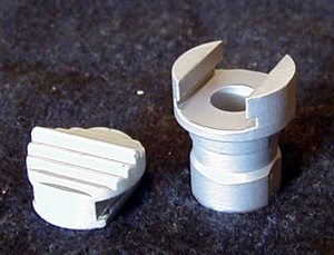
The housings come as a pair and include shipping and a pair of
cable ties to secure them in the throttle handle. They are only available in
the beadblasted finish but this can easily be painted black by the end user
as the finish is perfect for paint adhesion.
Casings are available for order - Contact IJ
|
|
|
|
|
We all know it, IJ the Übermeister is a lazy guy. After
having worked without stopping for the past 2 years doing Über mods so
we can enjoy our sims. He finally decided to invest in a CNC mill (computerized
milling machine for the profanes :) ) The main goal was to redesign the Ü2
concept to lower production costs while maintaining the same level of quality,
if not increase it! Today, the Über2 is discontinued and replaced by the
Ü2 NXT. The advantages are multiples:
- It's a good deal less expensive.
- It's adjustable in each axis for centre position.
- It's made from a better grade of aluminium (this allows IJ to make the
Nxt more "svelte" compared to the U-2.)
- It's made using the CNC so this allows IJ more freedom in the design.
- IJ is using a higher grade of bearings and providing Stainless mounting
hardware as the savings from the CNC are being in part passed onto the end
user.
- It's less expensive! did I say that already?.
As usual, Contact IJ
for prices and availability - Payment is done through Paypal.
|
|
|
|
|
Ian Johnston didn't stop with the Über Cougar, he pressed
further with the goal to create a "drop in mod" without any play and
without the transition near the centre axis. He designed the Über Ultra
and consequently the Über-1 to finally go into production with the Über-2
mod. The Über-2 mod has the same geometry of the Über-1 (never produced
except as a prototype) and is designed for Hall sensors only and will not work
with stock pots. If you don't own Hall sensors yet, they can be ordered at the
same time and a high level of communication is present between IJ and Cubpilot
ensuring that the sensors are sent from USA to your place and the Über
mod comes from Australia. Since both are "drop in" the user can assemble
all the parts to build his complete ÜberCougar mk2.
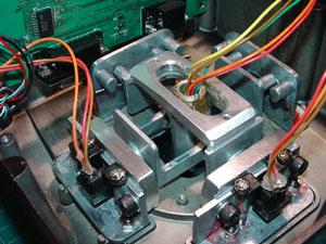
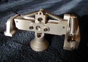
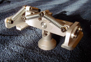
As you can see from the picture above, the Über-2 is a completely
new gimbal assembly and only requires the handle wiring harness from the stock
Cougar. IJ elected to use extension springs for a smoother feel of movement
and so far he's very impressed with the result. He says the Über-2 is just
so much easier in both rate and effort needed!
The mod comes with two sets of springs of different tension to suit as large
a panel of Cougar users as possible.
The Über2 production has been discontinued - check the
Ü2 nxt section if you are interested in such a mod.
|
|
|
|
|
The EvenStrain gimbals
are a complete replacement of the stock Cougar gimbals. The new system removes
the 4 transitions flats that some found annoying and lighten the stick loads
at the same time. The gimbals components are precision machined from 304 Stainless
Steel (except for the yoke plates for the first gimbals production run, which
were machined from 6AL-4V Titanium). Both X and Y axis are fully bearing supported.
EvenStrain has made use of non-traditional machining technologies and practices
in the design and manufacture of the gimbals and centering system, thus affording
him the ability to develop a compact and strong alternative to the stock Cougar
mechanicals.
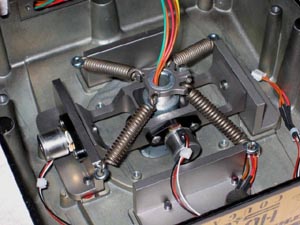
The centering system utilizes 4 extension springs to replace
the two stock torsion springs. The springs are kept in tension at all times
to provide positive stick centering. The stick loads of the EvenStrain Cougar
are 1/3 - 1/2 that of the stock Cougar, and of course the transition flat spots
are completely eliminated. The EvenStrain Cougar is designed to utilize only
Hall Sensors.
Greg "the Gimbal Meister" is now assembling the second
production run. The Cougar base as well as the lower stick shaft needs to be
sent to Greg at a certain point along the production for fitting and assembly.
The base is returned to the customer "ready to fly" and installed
with the Hall sensors. It's worth mentioning that Hall Sensors can be ordered
with the EvenStrain Gimbals for and additional fee if you still don't own them.
Greg is looking for spare lower stick shafts to accelerate the
EvenStrain turnaround, so if you are a U2 owner with a spare shaft and wish
to sell it to him, don't hesitate to contact EvenStrain.
Contact Greg for pricing and how to proceed if you want to order
the EvenStrain mod. Preferred payment is through Paypal.
|
|
|
|
|
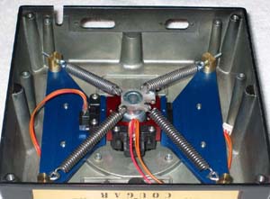
The EvenStrain lites are of the same concept as the original Evenstrain
gimbals but machined with other compenents to decrease costs. They are precision
machined from 6061-T6 aluminum and anodized. A true drop-in mod requiring a
minimum of tools and expertise. Supported by precision machined bushings. The
EvenStrain Lites will work with either the stock CTS pots* or CubPilot's HE
Sensors. Mounts for both pots and sensors are included in the gimbals kit. The
EvenStrain Lites completely eliminate the transition flats of the stock Cougar
gimbals as well as any center play.
*The use of used CTS pots is not recommended. Used pots are more
likely to be damaged by the sloppy stock gimbals, therefore making their use
in the EvenStrain Lites problematic. Greg strongly recommends the use of CubPilot's
HE Sensors with the Lites.
Greg can install the drop in mod himself into your Cougar for
a small fee. Please check Greg website
for further info and pricing.
|
|
|
|
|
Ernie "CubPilot" Smith decided one day to replace the
stock pots with Hall sensors to get rid of the spiking and increase precision
of his Cougar. So was born the Cougar+ HS Mod Kit. It's a high-end mod, using
high quality Hall Effect Angle Sensors. The sensors utilize a temperature stabilized
Hall Effect Sensing IC, specifically designed for feedback position sensing
applications in a wide temperature range. These sensors replace the stock pots
of the Cougar's X, Y, & Z-axis and offer something that the stock pots can't:
reliability and a cleaner output signal to the Cougar's electronics. The precision
of each axis is improved markedly over the stock pots, especially when compared
to pots that have seen some use and are starting to degrade. If you have no
idea of what a Hall Sensor is you can get more information about it on Cubpilot's
webpage.
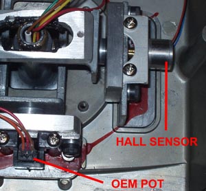
This kit will fit Cougars and ÜberCougars (as shown above)
and is mandatory in Über2 and Evenstrain Gimbals. It requires no modifications
to the Cougar's mechanicals. It attaches to the gimbal brackets utilizing the
stock pot's mounting holes and screws. There is some soldering involved with
the installation so you better have a soldering iron. Ernie also has a special
HS kit that can be installed on a stock, unmodded Cougar. He is also offering
a throttle kit for the TQS:
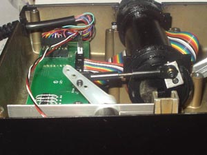
This Kit will replace the pot on the Throttle axis with the same
high quality Hall Sensor as used for the Joystick + HS Kit. The installation
does not require drilling, cutting or any other mechanical modifications to
the throttle base. Its design lends itself to the many different variations
of fixes that Cougar owners have employed to help to reduce the "sticktion"
that the Cougar's throttle exhibits in stock form. Side loads from a loose throttle
shaft in its' bearing or from drag adjustments of the throttle will not be transmitted
to the Hall Sensor. I have left the four inner screws out and only use the four
outer (corner) screws to hold the bottom cover of my throttle base on and the
Hall Sensors response in the Foxy Analyzers are rock solid. There is some soldering
required for this installation and it cannot be avoided.
Don't forget to read Jame's excellent review of Cubpilot's Hall
sensor here.
Contact Ernie with the following link according to your request:
HS kit info request
|
|
|
|
|
After a long period of silence, NN_Dan finally surprised the french
community (and our as well) by opening orders for a first batch of 20 units.
His mod is based also on scamp mod, as the evenstrain and uses 4 extension springs
for the centering system. It completely removes the transition flats of the
stock Cougars and provide an increase in force according to the amplitude of
the sick mouvement. Needless to say, there's no play left in this mod except
maybe the play introduced by the threads of the handle
(as in any other play mod)
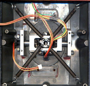
NN_Dan plans on using the stock potentiometers for his mod since
he believes that they are prefectly suitable for the Cougar if the play problem
have been addressed (and I agree) Although it's possible to adapt the mod with
Cubpilot's Hall that need to be ordered from Cub and sent to NN_Dan. A slight
note of warning is needed here, if you order the mod for stock pot, then adapting
the mod for Halls sensors is not an easy job and best done directly by NN_Dan.
The Cougar base needs to be send to NN_Dan in France so he can modify it and
the centre shaft. So it's not a drop in mod. He also install new stock pots
or Hall Sensors from Ernie in the modded Cougar. After that the base ready to
use is sent back to the customer.
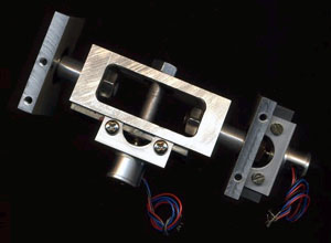
Price is around 250 euros without the Halls sensors and without
shipping. The first batch is now closed but he might consider opening future
batches after this one.
Forum topic on C6:
(in french)
Contact directly NN_Dan
|
|
|
|
|
Eagle, a dutch electonic engineer developped a force controlled
pressure sensitive Cougar in his backyard.
All Cougar internal part are replaced with a force sensor meaning
that all native Cougar problems will be solved at once: no play, no springs
problem, no pots problem. As such it will be a drop in mod.
The pressure driven Cougar will have a minimum distance of mouvement on purpose,
as the real F-16 stick. The word play might be used here, but without its negative
meaning! Indeed having such a small amount of mouvement allow the pilot to check
and confirm easily the direction in which he applies pressure.
The mouvement is induced by how hard the user apply pressure on the stick and
even if that will require an adapting period, the bottom line is an increase
in overall precision, especially in energy managment. Without surprise the FCC
will be ideally suited for jet jockeys flying mostly the F-16 although it's
suitable for any jet flight sim. Flying prop driven aircraft, although possible,
is less suitable.
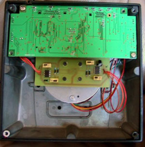
Eagle prototype has been displayed at the LLTM 2003 (Low Land
Tiger Meet) and some lucky fews (including real F-16 pilots and me) had the
opportunity to try it out. All opinions were positive. My impression is that
it is very close to the real F-16 stick. The first time I flew the F-16 simulator
(block 15) in the belgian airforce, I had a FLCS and directly after coming back
from the base, I went fishing for a F-22 - the stronger stick on the market
at that time. From these days, I became a member of the "the harder the
better" community as far as joysticks are concerned ;)
By trying the FCC prototype, I found exactly the same sensation that I discovered
in the F-16 simulator. Precision of mouvement, stability in all direction, easier
energy managment.
The FCC, as the real F-16 stick allows directionnal play to give
a tactile feedback as in which direction the pilot moves the stick. There are
actually 4 possibilities with the FCC: No play at all, light play introduced
by strong springs, more important play introduced by smooth springs and the
fourth possibility is to replace the springs by rubber O-rings that give a special
feeling. All included in the package. The FCC is really easy to install - as
with any drop in mod, the harder is to get the original Gimbals out of the Cougar
base. The FCC is delivered with a special Cougar plate.
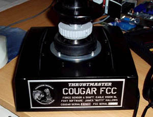
At this time about 100 FCCs have been sold to the community all
over the world. Arend has made some
units in advance and there's a high chance that the FCCs are delivered right
after order. In any case Contact Arend
for information about future runs, availability and price which should be around
250 euros.
Here are some reviews for the FCC: Red Dog's
Preview and Mirv's review.
|
|
|
|
|
Well, Covering the Cougar is not
really an hardware mods but since our babies are all metal and black metal with
that, it's kind of annoying to clean the dust every week from our joystick.
Ryan "Kosmo" Cowley and
his wife came to the rescue with the release of Hotas Covers: They are high
end Cougar covers embroided with the name of the pilot and featuring two small
remove before flight tags. Kosmo also makes covers for other HOTAS system. I
must say I jumped at the occasion to have a sort of protection for my beloved
Cougar and I have mine almost since the first day they are available. Today,
every guest entering my room is flabbergasted not by my setup but by my Hotas
Cover ;) Pretty nice touch IMHO.
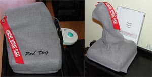
Head over to Kosmo website
for information and ordering. Preferred payment through paypal. It's maybe worth
mentionning that SimWare (in Belgium) is assuring
distribution of the Hotas Cover in Europe.
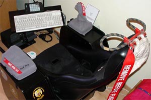
|
|
|
|
|
No need to introduce Realsimulator to you guys. They are a commercial
company making outstanding parts for cockpit builders amongst us (ICP, MFDs,
rudders, aces2 seats, and soon full cockpits).
The company announced a force mod for the Cougar available in two versions:
FSSB R1 and FSSB R2. The difference between the two, besides the price, being
the quality and life cycle of the parts used. But I'll let James talk about
it since I haven't tried the FSS. Read his review here.
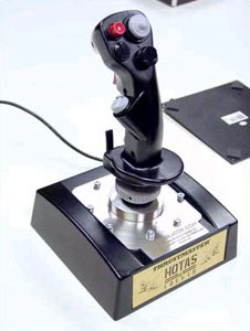
Visit Realsimulator
for further information regarding availability, prices,...
|
|
|